When a drive, controller, or HMI stops working, the fault often traces back to a single printed circuit board, and frequently to a handful of components on that board. Yet the default response in most facilities is to quote a whole new unit.
For older equipment, that reflex is expensive. It's also sometimes impossible: once a platform goes obsolete, there is no new unit to buy. Circuit board repair is what keeps that equipment running.
This guide covers what industrial PCB repair actually involves, the failure modes we see most often, and how to judge whether a board is worth repairing.
What Industrial PCB Repair Covers
Industrial circuit board repair means diagnosing and fixing a board at component level rather than swapping the assembly. In automation equipment that typically means:
- Drive control boards: the logic and gate driver sections of VFDs and servo drives
- Power boards: rectifier sections, DC bus components, IGBT driver circuits
- I/O and communication cards: PLC modules, fieldbus interfaces, encoder feedback cards
- HMI mainboards: backlight drivers, touch controllers, power supply sections
- Motion controller boards: axis cards, interpolation boards, robot controller assemblies
The work is the same discipline in each case: identify the failed component, understand why it failed, replace it with a correctly specified part, and verify the board under realistic load.
Common Circuit Board Failure Modes
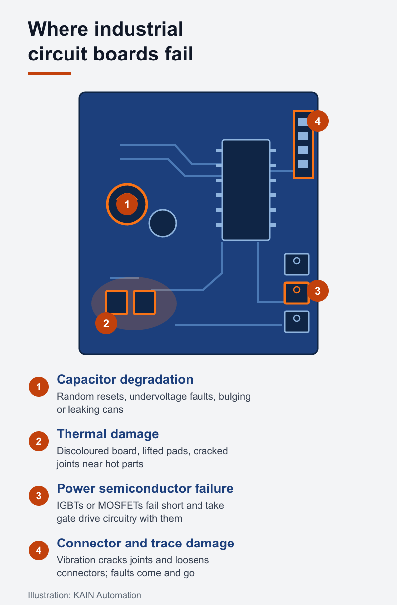
Boards rarely fail randomly. Most failures fall into a small number of categories, and each leaves a recognizable signature.
Electrolytic Capacitor Degradation
The most common failure in any board carrying a power section. Capacitors dry out with heat and age, losing capacitance and gaining equivalent series resistance. Symptoms include random resets, undervoltage faults, ripple on supply rails, and visible bulging or leakage.
Thermal Damage
Heat is the underlying cause of a large share of board failures. Look for discoloured PCB material, lifted solder pads, cracked solder joints around high-current components, and discoloured or charred resistors. Thermal damage usually points to a cooling problem elsewhere: a blocked fan, a clogged filter, or a cabinet running hotter than it should.
Power Semiconductor Failure
IGBTs, MOSFETs, and rectifier diodes fail short or open. When a power device fails short, it often takes gate driver circuitry with it, so testing must extend past the obvious failed part.
Connector and Trace Damage
Vibration loosens connectors and cracks solder joints. Corrosion from humidity or contamination attacks traces and pads. These faults are often intermittent, which makes them harder to diagnose than an outright failure, and more disruptive to production.
Firmware and Memory Corruption
Not every board fault is physical. Corrupted EEPROM, dead backup batteries, and firmware issues can present as hardware failure. Checking this early avoids replacing parts that were never faulty.
The Diagnostic Process
A structured process matters more than any single test. Ours runs roughly as follows:
- Intake and history. What was the equipment doing when it failed? What fault codes appeared? Has this happened before?
- Visual inspection under magnification. Burn marks, bulging capacitors, corrosion, cracked joints, lifted pads, evidence of prior repair attempts.
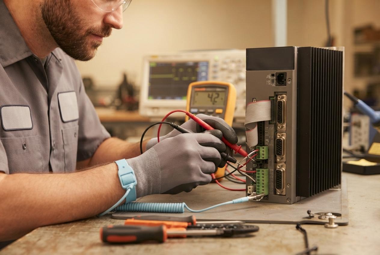
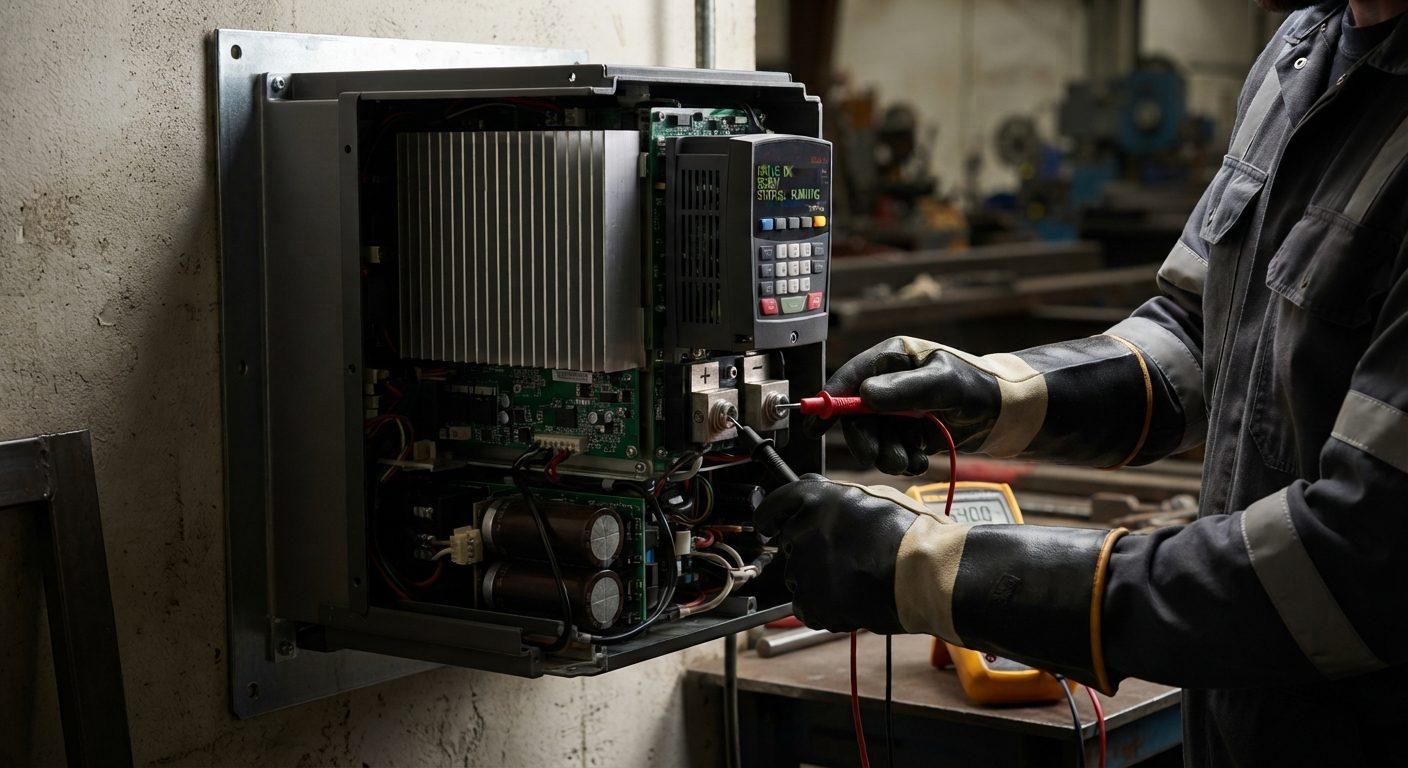
- Component-level testing. In-circuit and out-of-circuit measurement of suspect devices. ESR testing on electrolytics, diode and transistor testing on power devices.
- Power-up under controlled conditions. Current-limited supply, monitoring for shorts and abnormal draw before applying full power.
- Signal tracing. Oscilloscope work on gate drive, feedback, and communication sections to confirm the board behaves as designed.
- Repair. Component replacement with correctly specified parts, proper rework technique, and ESD control throughout.
- Load testing. Verification under realistic conditions, not just a bench power-up.
That last step separates a real repair from a parts swap. A board that powers up isn't necessarily a board that will survive a production shift.
When Circuit Board Repair Makes Sense
Repair is usually the right call when:
- The equipment is obsolete or the replacement lead time is long. If a new unit is 6–8 weeks out, or no longer manufactured at all, repair may be the only realistic option.
- The failure is localized. One failed section on an otherwise sound board is a straightforward repair.
- The board is integrated into a tuned system. Replacement often means reprogramming, re-tuning, and re-commissioning, costs that don't appear on the hardware quote.
- You need it back quickly. Component-level repair typically turns around in days rather than weeks.
When Replacement Is the Better Call
Be realistic about the cases where repair isn't worth it:
- Widespread thermal damage. If the board substrate itself is damaged across multiple sections, repair reliability drops.
- Repeated failures on the same board. Recurring faults usually mean the root cause is external: supply quality, cooling, or load. Fix that first, or the next repair fails too.
- Multiple failed sections plus available replacement. If power, control, and communication sections have all failed and a new board is in stock at reasonable cost, replacement is cleaner.
- Safety-critical applications with certification requirements. Some applications require certified assemblies.
Reducing Board Failures Before They Happen
Most of what kills industrial circuit boards is environmental, and most of it is preventable:
- Manage heat. Clean filters, verify fan operation, and check cabinet temperature against equipment ratings.
- Control contamination. Dust and conductive debris cause shorts and block cooling. Appropriate enclosure ratings matter.
- Address vibration. Mount equipment away from vibration sources and check terminal tightness on a schedule.
- Condition your power. Surge protection and line reactors protect against transients that destroy input sections.
- Watch humidity. Condensation and corrosion do slow damage that shows up as intermittent faults months later.
Our predictive maintenance guide covers how to catch these conditions before they cause a failure.
What to Send With a Board for Repair
Turnaround improves substantially when the repair shop has context:
- The complete unit where practical, rather than the bare board, as it allows testing in situ
- Model and serial numbers, and firmware version if known
- The fault codes or symptoms observed
- What changed before the failure: a power event, a new load, a maintenance action
- Any previous repair history on the same unit
Circuit Board Repair Across Ontario
KAIN Automation provides component-level circuit board and industrial electronics repair for manufacturers across Ontario, covering drive boards, controller cards, I/O modules, and HMI assemblies from all major automation platforms.
If you have a board you were about to scrap, it's worth a diagnostic first. Get in touch and we'll tell you what we find.